Design of a Pumping System for Water Transfer from a Lake to an Elevated Reservoir
Design of a Pumping System for Water Transfer from a Lake to an Elevated Reservoir
1. Abstract
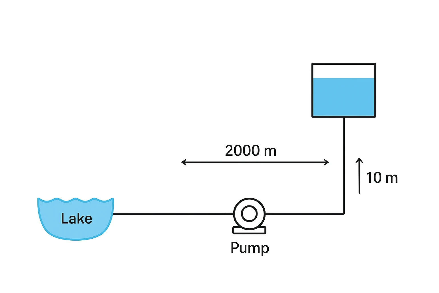
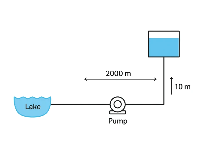
This study specifies the hydraulic and mechanical requirements for a pipeline and pump system designed to transfer water from a lake (source) to an elevated reservoir. The reservoir is located 2000m away and is elevated 10m above the lake's water level. Assuming a required flow rate (discharge) of Q=50m3/h, the preliminary design calculations yielded the following key results:
Optimal Pipe Diameter: Approximately 110−125mm.
Total Dynamic Head (Htotal): 30.8m (including 20.8m of frictional head loss).
Nominal Pump Motor Power (Pmotor): Approximately 6kW (assuming 70% efficiency).
Keywords: Pumping System Design, Head Loss, Darcy-Weisbach Equation, Pump Selection, Hydraulic Transport.
2. Introduction and Design Parameters
Water transfer systems are a vital component of infrastructure, with efficiency heavily relying on the accurate selection of the pump and the transmission pipeline. This engineering design aims to establish the fundamental criteria for choosing the appropriate pump and the optimal pipe diameter to convey water from the natural source to the elevated reservoir, overcoming both the static elevation and frictional head loss.
2.1. Basic Design Parameters
| Parameter | Symbol | Value | Unit |
|---|---|---|---|
| Pipe Length | L | 2000 | m |
| Reservoir Elevation (Static Head) | Helevation | 10 | m |
| Required Flow Rate (Assumed) | Q | 50 | m3/h |
Export to Sheets
3. Methodology and Hydraulic Calculations
The design relies on the principles of fluid mechanics and the application of Bernoulli's equation (the law of conservation of energy) to determine the Total Dynamic Head (Htotal) required by the pump.
3.1. Flow Rate Conversion and Velocity Estimation
The required flow rate is converted from m3/h to m3/s for subsequent calculations:
Q=3600 s/h50 m3/h≈0.0139 m3/s
An ideal water velocity of v≈1.5 m/s is assumed to balance erosion and energy loss.
3.2. Pipe Diameter Selection (D)
The required diameter is calculated from the flow rate and assumed velocity (Q=A⋅v):
D=πv4Q

≈0.108 m≈110 mm
Design Decision: A pipe diameter of 110mm, or the closest commercial size 125mm, is selected. (Calculations proceed with D=0.11m for preliminary estimation).
3.3. Frictional Head Loss Calculation (hf)
The major head loss due to friction is calculated using the Darcy-Weisbach Equation. (A preliminary friction factor of f=0.02 is assumed).
hf=fDL2gv2
hf=0.02×0.112000×2×9.81(1.5)2≈20.8 m
3.4. Determining the Total Dynamic Head (Htotal)
The total head required is the sum of the static elevation and the friction loss:
Htotal=Helevation+hf=10 m+20.8 m≈30.8 m
4. Pump Selection and Power Requirement
4.1. Hydraulic Power (P)
The hydraulic power (power required to lift the water) is calculated using the formula:
P=ρgQHtotal
P=1000×9.81×0.0139×30.8≈4200 W≈4.2 kW
4.2. Pump Motor Power (Pmotor)
Assuming a typical pump efficiency of η=70%:
Pmotor=ηP=0.74.2 kW≈6 kW
5. Results, Conclusion, and Recommendations
5.1. Summary of Engineering Results
| Parameter | Value |
|---|---|
| Required Total Dynamic Head (Htotal) | 30.8 m |
| Proposed Pipe Diameter (D) | 110−125mm |
| Nominal Pump Motor Power (Pmotor) | 6 kW |
| Type of Pump Required | Centrifugal Pump |
Export to Sheets
5.2. Conclusion
Transferring water at the flow rate of 50m3/h necessitates a Centrifugal Pump capable of generating a Total Head of at least 30.8m with a minimum motor power of 6kW. Pipes with a diameter of 110−125mm are required to maintain acceptable flow velocities.
5.3. Practical Recommendations
Refinement of Friction Factor (f): The friction factor should be accurately determined using the Moody Chart after selecting the final pipe material (e.g., PVC, Ductile Iron).
Inclusion of Minor Losses: Minor losses resulting from valves, elbows, and fittings should be calculated and added to the total head for final pump sizing.
System Protection: The suction line must be equipped with a Strainer/Filter to prevent debris from entering the pump. A Check Valve (Non-Return Valve) must be installed immediately after the pump to prevent backflow.