Firefighting System Operation Steps for the Three Fire Pumps
Automatic Fire Pump System Operation: Details and Readiness
The pump-based fire suppression system is the lifeblood of any facility, ensuring a reliable and automatic response upon the detection of danger. The system relies on a precise pressure sequence that guarantees the correct pump activates exactly when needed.
I. The Automatic Sequence of the Three Pumps
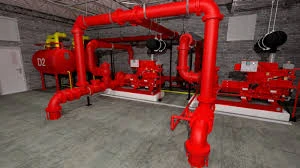
The fire protection system relies on three main pumps operating sequentially to ensure continuity of pressure and flow based on the network's pressure drop:
1. Jockey Pump – Pressure Maintenance
Function: Maintains the normal system pressure (rated pressure) and compensates for minor leaks or pressure variations caused by temperature changes.
Startup Set Point: Pressure drops slightly to $\mathbf{130}$ PSI ($\mathbf{9}$ bar, typically 10-15 PSI below the nominal pressure).
Shutdown Mechanism: Stops automatically upon restoring the system pressure ($\mathbf{145}$ PSI or $\mathbf{10}$ bar).
2. Main Pump (Electric) – Primary Firefighting
Function: Provides the required high flow and pressure for actual firefighting (e.g., sprinkler activation or fire hydrant use).
Startup Set Point: Pressure drops significantly to $\mathbf{115}$ PSI ($\mathbf{8}$ bar), following a short time delay of approximately $\mathbf{7-8}$ seconds.
Shutdown Mechanism: Must be shut down manually from the control panel only. This ensures continued water supply during an emergency.
3. Diesel Pump (Standby/Emergency)
Function: Serves as a critical backup in case of electric pump failure or loss of main power supply.
Startup Set Point: Pressure drops to the lowest setting, $\mathbf{100}$ PSI ($\mathbf{7}$ bar), following a slightly longer delay of approximately $\mathbf{12-13}$ seconds.
Shutdown Mechanism: Must be shut down manually from the control panel.
II. Pump Selection and Performance Criteria (NFPA 20 Compliance)
Fire pump selection is governed by strict standards to guarantee reliability under maximum conditions:
Performance at $\mathbf{150\%}$ Flow: When the pump operates at $150\%$ of its rated flow, the discharge pressure must not fall below $\mathbf{65\%}$ of the rated pressure. This confirms sufficient working pressure is available even under peak demand.
Shut-off Head (Churn Pressure): When the pump runs with no flow (shut valve), the pressure must not exceed $\mathbf{140\%}$ of the rated pressure. This prevents damage to system components (sprinklers, valves) from overpressure.
Certifications: Pumps and associated equipment must be listed and approved by recognized international bodies such as UL (Underwriters Laboratories) or FM Global (Factory Mutual).
III. Essential Components and System Readiness
For effective automatic sequencing, the system relies on key technical components and requires mandatory readiness checks:
A. Technical Components
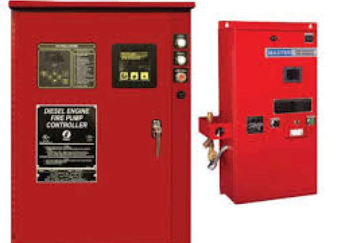
Controller: The system's central brain, which receives signals from pressure switches and executes the timed, logical start sequence.
Pressure Switches: Sensors that define the highly accurate cut-in and cut-out points for each pump.
Test Header: An outlet used annually to conduct flow tests, simulating actual fire conditions without discharging water inside the facility.
B. Pre-Startup Readiness Checks
Water Source: The water supply (tank or source) must be sufficient and available.
Valves: All isolation gate valves on suction and discharge lines must be fully open (excluding the test valve).
Power and Fuel: Electric power must be available, and the diesel fuel tank must be full.
Control Mode: All control panels must be set to the "Auto mode."
IV. Regular Testing and Maintenance (Ensuring 100% Readiness)
Routine maintenance and testing are indispensable for maintaining continuous system readiness:
A. Routine Inspections
Weekly Run Test: All pumps (Electric and Diesel) must be run weekly for a minimum of $\mathbf{30}$ minutes. This ensures mechanical components are lubricated and functional, and for diesel pumps, it warms the engine and circulates fluids.
Diesel Check: Diesel fuel level, oil quality, and engine coolant must be checked regularly. The efficiency of the battery chargers, which are crucial for reliable instant startup, must also be verified.
B. Annual Maintenance and Documentation
Annual Flow Test: The actual pump flow is measured and compared against the original performance curve to confirm there is no performance degradation over time.
System Log Book: A detailed log of all operations (weekly run or emergency starts), test results, and any maintenance must be maintained. These records are essential for regulatory compliance and performance tracking.
Adherence to these detailed operational and maintenance steps guarantees that the fire suppression system remains the effective and reliable first line of defense when needed.